Thursday, December 31, 2020

Fix the Block Insert issue

The issue:

Block insert with the keyboard shortcut I

This has been so annoying that I often find ways to not insert blocks anymore.

There are work arounds that make the problem go away.

you can use the command.  CLASSICINSERT

What I found and used was way to easy and sweet to not document for my own reuse.

I normally just type I and boom the insert dialogue box pops up.

Since 2019 this new Insert command often just hangs.  Which sucks. 

Autocad has this acad.pgp file that is the old school way to load command line aliases

I found this solution here: (not sure if that link will remain valid, so I just copied the text.)

https://forums.autodesk.com/t5/autocad-map-3d-forum/acad-pgp-command-alias-editor-in-map-3d-2019/td-p/8590554

To edit the pgp file in use by your session, at the command line, type this:

(startapp "notepad" (findfile "acad.pgp"))

this will pop up notepad, where you will search for 

I,     *INSERT and swap it out with  *CLASSICINSERT

while you are there you might as well swap out 

AR,    *ARRAY with the old school     *ARRAYCLASSIC

Save the file and close it.

Back in cad type REINIT


and make sure to click PGP file.

Cheers

Thursday, November 5, 2020

DATAEXTRACTION

 PROBLEM:  Old Land Desktop points as blocks that you would like to use as civil points


You can use the command DATAEXTRACTION

This command allows you to select the point block and extract the attributes to a csv file.


Choose a file name and save path

Next select the source.  I used objects in the current drawing.


I selected the properties of the block that I want to export.


I then sorted the columns how I would like to see them (you could also do this in excel)


Once this file is created you can open and manipulate the data however you choose and import into Civil as ponts.


Tuesday, March 29, 2016

corrective instrument

here are the links that I am always looking for...

Brown County ROD (my most impacted county)

http://www.co.brown.wi.us/departments/?department=e7fb85d94ba9&subdepartment=773844d034b1

Corrective Instrument

Instructions for the Wisconsin Electronic Real Estate Transfer Return (eRETR)

https://ww2.revenue.wi.gov/GenericFile/help/eRetr/detail.htm

Tuesday, March 15, 2016

Upgrade to Civil 2016

I copied all the files from the folder:  

C:\ProgramData\Autodesk\C3D 2013\enu\Survey

To this folder:

C:\ProgramData\Autodesk\C3D 2016\enu\Survey

This copied the figure prefix and the linework code set

Note:  I did NOT overwrite any files.

Next start a new Database
·         Right click on the new database and “Edit Survey Database settings”
·         The biggie is set the units to “US Foot”
·         Also unclick all the measurement corrections.


That I believe completes the setup

Tuesday, March 8, 2016

Object class

While working with CAD information, I came across a file that may or may not have been created in cad but in some other GIS format.  I have no idea.

While working with OD can be a pain in the butt, there are tools out there that help.  My limited knowledge of Map doesn't help.  One tip was to export the file to a SDF file (Autocad version of GIS)

This drawing file had 2 classes attached to the object in the drawing that had the Object Data attached.

One class was STRUCTURES and it was attached to a point:


The second class was PIPES which was attached to a polyline:


You can see the object classes in the Map Explorer view:


So now you have all this data and you want to add some new classified objects.

Simple ~ right click and select Create Classified Objects...


Object Data commands available

_ADEDEFDATA

_ADEATTACHDATA

_ADEEDITDATA

_MAPDIGISETUP

_MAPDIGITIZE

Copied straight out of the help area (so I can find this again when I need it)

3. Object Data commands available
Currently there are only five special commands in AutoCAD Map 3D to work with Object Data:
1. _ADEDEFDATA to create and edit Object Data descriptions.
This command is used to create Object Data descriptions composed of OD name that is unique within the DWG file (up to 25 characters) and value fields of type integer, char, point or real. The fields are defined with unique within one OD (up to 31 characters) names, descriptions (up to 40 characters) and default values (up to 132 actual characters though character fields are defined as 254 characters after export).
Cyrillic characters can be used in OD names and OD fields.
There is no limit of Object Data descriptions in DWG file. The number of fields in one OD is also unlimited. Real files observed to contain more than a hundred OD descriptions and more than thirty fields in one OD.
This command also allows Object Data descriptions editing – rename OD, remove descriptions, remove fields, change field descriptions and default values, add new fields.
2. _ADEATTACHDATA to attach/detach Object Data to/from graphic elements.
This command is used to attach Object Data to selected graphic elements, remove attached Object Data and define field values.
Several OD including identical can be attached to one graphic element.
The option of the identical OD overwriting is available, i.e. one can choose whether to remove the previous OD record or to create a duplicate.
The allowed number of OD per graphical element is not determined.
3. _ADEEDITDATA to edit and add/remove similar Object Data.
This command makes it possible to browse the Object Data attached to the specified graphic element, examine and edit the field values. It is also possible to add similar OD attached to this graphic element, remove OD, browse all duplicate OD and edit field values.
4. _MAPDIGISETUP to setup drawing with simultaneous Object Data attachment.
This command is used to determine a graphical element entity class (block, polyline, 3D polyline) to draw, the layer for this element, name and insert options for blocks, width and line type for polylines, the Object Data immediately attached to the element.
This command only partially refers to Object Data commands because Object Data attachment to the drawn elements is optional.
This command makes it possible to describe only one parameter set for drawing of single type of graphic element with simultaneous attachment of corresponding Object Data at a time. In other words, when describing a new drawing parameter set with OD the previous set is deleted. Consequently, it is impossible to create objects menu for drawing with OD using this command.
5. _MAPDIGITIZE to draw with simultaneous Object Data attachment.
This command is used to draw graphic elements defined with _MAPDIGISETUP and define Object Data field values when creating these elements.
Object Data attached to the elements and its fields values are shown by Map 3D in AutoCAD Properties palette (_PROPERTIES) after the graphic elements are selected. This palette allows editing these fields values – similarly to other properties shown in the Properties palette.
This helps to see presence/absence of OD attached to the graphic elements as well as to browse, input and edit OD field values. However, these capabilities are available only for preliminarily selected file elements. Besides, when selecting two or more elements with different OD, the information about OD is not displayed in the Properties palette. Also, OD is not used in Quick Select (_.QSELECT).

Filter

command: filter

problem:  I had a bunch of text that I wanted to get rid of.  It came from an import of some GIS data that had a bogus style.  The text string I wanted to get rid of was 934-405.  Under select filter I selected "text value" and entered the value in the X line and then added it to the list.  Net just click apply.  You now have the option to select objects (you can use all or window a selection)


It worked great, after all these years, I either forgot about this or never knew that it existed.

That is all you need to run a simple filter

Friday, September 18, 2015

parcel table expression

So I keep having this reoccurring issue, on how to get my R/W TOTAL ACRES column in the WisDOT "SCHEDULE OF LANDS & INTERESTS REQUIRED " table
 to read in acres, it defaults to sq.ft.


Click Expressions to highlight

Right click on Total RW


{Parcel Area}/43560 + {Existing RW}

Friday, March 6, 2015

FLATTEN

So after I was able to import the object data from some shp files, I soon found out that I just couldn't copy the txt to different drawing.  What I found was that the flatten command does wonders with all this object data text.

Plain Text from Object Data

This works sweet to extract plain old txt from object data.

I found the super helpful article here.  http://map3d.wordpress.com/

I take no credit for the information that I am going to copy to my blog so that I can find it in the future.

Have you ever imported ESRI SHP files or other GIS files and need to create some simple text labels for that data? Do you have some object data attached to entities that you now need to display that data in the drawing? One method of displaying or labeling those entities is by using Map Annotation Blocks or use FDO. But what if you need something quick and as plain text?
I see questions on how to do this or can Map3D do this. Yes it can be done. You can use the Map3D display manager to query the current drawing then create a “Map3D” text style in the display manager.  
So lets look at the drawing I have for the example.
OD_Info
It’s a simple parcel map imported from an SHP file and object data was created on the import. What I need is to label each parcel  from that object data with the Watershed1 value.
The first step is opening the Map3D Task Pane and using the Display Manager tab. If the task pane is not open use the command MAPWSPACE and select ON at the command line.
Add_Layer
Now click on the Data icon in the display manager, scroll down to “Add Drawing Data”  then select “Query Current Drawing”
The Define Query dialog will open allowing you to define the query. I want to query on my object data so I select “Data” for the query type. The Data Condition dialog will open allowing me to select the data to query on. I select “Object Data” make sure I have the correct Table listed (Parcels), select the field I want the label to display (Watershed1) then for the Operator and Value I use = (equal sign) and *(the wildcard expression).
query
As soon as I click OK it populates the upper part of the Define Query dialog. Clicking OK in this dialog takes me back to my drawing.
I now have a new object or a Map3D Display Manager Layer listed in the Task Pane.
new_Layer
The next step is to add  a text style to display the text that is being queried in on that new layer. TIP: When we say Layer in Map3D Display Manager it is NOT an AutoCAD layer and has no relationship to the layer manager or any of the AutoCAD layers.
To create our text style for our data labels we right click on the layer name in the Display Manager and select “Add Style” then “Text”.
Add_TextStyle
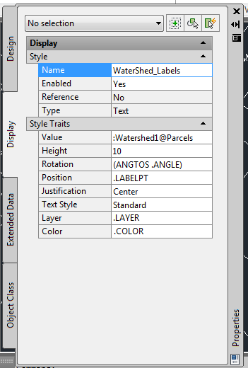
We now have another object in the Display Manager under the “Current Drawing Element” layer named “Text Style”.  Highlight the “Text Style” in the Display Manager and look at the properties of it in the property palette. (Right Click and select Properties to open the property palette.)  This is where we tell it to display the values from the Object Data table.
Select the Value- Text Label to show the ellipsis icon (the 3 dots) Click on the icon to open the Expression Chooser. 
TextStyle_default
In the Expression Chooser, expand the tree to get to the Object Data field to label from. Select the field and click OK.
expression 
Back it the Property Palette set the Height as needed and any other property you wish. Notice I changed the Height to 10 and provided a better fitting name for the text style.
Text_Final
Notice as you start to make changes in the property palette for the Text Style the labels change instantly allowing you to see the changes as you make them.
Labed_Drawing
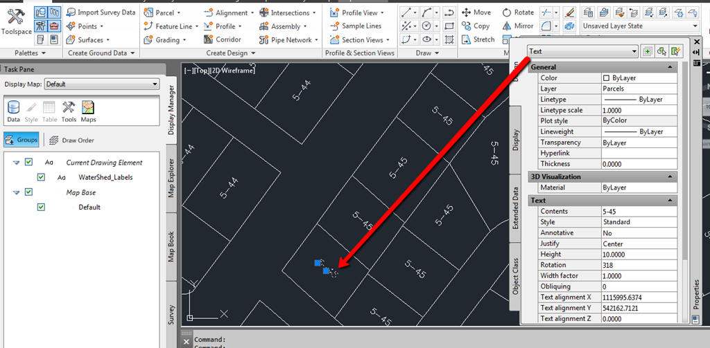
Now back in the drawing we have labels for all of the parcels and they are plain AutoCAD text objects. No FDO text style, no Civil3D label and no Map Annotation blocks.

Monday, August 4, 2014

THOSE DAMN ATTRIBUTES!!!

For those occasional times when you would like to automatically import OD

I found this nugget of info that I have now used many times.  Thanks you source!

First, use 'Mapimport' to bring in your closed polylines with object data.

then:
1- 'mapanntemplate'  (don't enter the quotes - you'll get a dialog box, when you hit ok, it'll open the block editor)
2- 'mapanntext' (then I hit 'enter' for new text.  You'll get a dialog box asking for information for you to supply for the label.  Under the 'value' box, you can specify a field from your object data to be supplied.  When it asks for the insertion, i always use 0,0; which inserts the text right where i need it inside the polylines.).  At that point, i close the block editor, saving my changes on the way.
3 - 'mapanninsert' (check the template you created, select your polylines, and voila!  Labels!

if the labels need to be tweaked, use the 'mapanntemplate' again, to edit the template contents, such as size, layer, etc.; then run the 'mapannupdate' command to have those changes reflected.

Tuesday, December 11, 2012

Translating ortho images

Here is a quick and easy solution to a problem I encounter every time I need to insert an orthographic file that is based on a differing coordinate system.

Here is a link to the article from Master Graphics.  Thank You Master Graphics!!!

In the event that this page is removed the key commands are.

If you are in the same coordinate system and units this should work.

1.  MAPIINSERT
Note: the Map Image Insert command will NOT transform the coordinates or units of an image if they
differ from the drawing coordinate system or units. Be aware of the difference between US feet and
International feet.

If you have differing units or coordinate systems, you will need to follow a few steps.

  1. Start a new drawing with the same units and system as the image file you are trying to utilize.
  2. Use MAPIINSERT to insert the raster image into the new drawing you just created with matching values.  save and  close this drawing.
  3. Go back to your project drawing and verify that the drawing units that you are working in are established in Civil 3D
  4. Type  MAPWSPACE  on the home tab clich attach source drawing, you will need to establish a drive alias (a path to the location of your image file) the alias name can be anything you call it but you will need to browse the file location of the image file. Add the path and then Close the command 
  5. Now you need to add that information to your drawing.  type adequery  Click location and set boundary to ALL then click OK, next set the query mode to DRAW and click Execute Query.
  6. This should bring you file in ZE and you should see it.  The last step is to DETACH the drawing from the map explored tab ( WMAPSPACE )


I will also include some sweet data sources for Wisconsin.

Wisconsin View follow the link to Imagery Downloads.  You will need to sign up and or sign in with your email address.  From my experience all the files are in wtm or wisconsin transverse mercator.

 Wisconsin Historic Aerial Image Finder allows you to search aerial photographs of Wisconsin from 1937-41.  Here there is no real correlation with the images, you are on your own.


Wednesday, November 28, 2012

OD

I found this helpful when trying to annotate some blocks with OD

Here is the link  

1- 'mapanntemplate'  (don't enter the quotes - you'll get a dialog box, when you hit ok, it'll open the block editor)
2- 'mapanntext' (then I hit 'enter' for new text.  You'll get a dialog box asking for infomation for you to supply for the label.  Under the 'value' box, you can specify a field from your object data to be supplied.  When it asks for the insertion, i always use 0,0; which inserts the text right where i need it inside the polylines.).  At that point, i close the block editor, saving my changes on the way.
3 - 'mapanninsert' (check the template you created, select your polylines, and voila!  Labels!

if the labels need to be tweaked, use the 'mapanntemplate' again, to edit the template contents, such as size, layer, etc.; then run the 'mapannupdate' command to have those changes reflected.

Tuesday, July 10, 2012

Tuesday, May 22, 2012

What Stinking feet is it anyways??

http://www.ngs.noaa.gov/faq.shtml
What are the "official" conversions that are used by NGS to convert 1) meters to inches, and 2) meters to feet?
[This explaination courtesy of Ed McKay]
First, remember this rule: There is only one meter, BUT, there are
two types of feet.
 
The two types of feet are:

 1. The U.S. Survey Foot
 It is defined as: 1 meter = 39.37 inches.
 If you divide 39.37 by 12 (12 inches per foot), you get the
 conversion factor: 1 meter = 3.280833333... U.S. Survey Feet.

 2. The International Foot
 It is defined as: 1 inch = 2.54 centimeters.
 If you convert this to meters and feet, you get the conversion
 factor: 1 International Foot = 0.3048 meters.

These two conversion factors produce results that differ by 2 parts per
million; hence for most practical work it does not make any difference
to the average surveyor which one is used since they usually do not
encounter distances this large. For example, converting a distance of
304,800 meters (about 1,000,000 feet) to feet using the two conversion
factors, these are the results:

 304,800 meters = 999,998.000 U.S. Survey Feet
 304,800 meters = 1,000,000.000 International Feet

A difference of 2 feet in 1 million feet.


Monday, April 16, 2012

Sending Civil 3D drawing to non civil 3D user

Low-Tech Collaboration
Copied from AUGI Link

There are all sorts of new, fancy ways to share your Civil files and documentation internally and with clients. Let’s not forget, however, the many ways available to us over the years. The first of these methods I’d like to explore is through working with the PROXYGRAPHICS system variable.

Although not a complete solution, understanding how the PROXYGRAPHICS setting works will be your first round of defense for sharing intelligent AutoCAD® Civil 3D® files with your coworkers, subcontractors, or clients not utilizing Civil 3D for their own efforts. Proxy graphics store the last viewed image of Civil 3D objects, which lets users view your drawing without modifying the original objects. Also, they only hold the graphical representation of the current, active viewport when the drawing file is saved.

Setting up the PROXYGRAPHICS system variable is easy enough. Simply type it in at the command line and set it to “1.” The default is “0” and we’ll explore the differences in this section as a point of comparison. With PROXYGRAPHICS set properly, SAVE your drawing.


Figure 1: A drawing file created with Civil 3D, saved with PROXYGRAPHICS set to “0” and opened in AutoCAD®. Note the Civil 3D entities are broken. (Compare with Figure 2.)


Figure 2: A drawing file created with Civil 3D and saved with PROXYGRAPHICS set to “1” and opened in AutoCAD.

It isn’t that simple, though, as there is an immediately apparent downfall of using PROXYGRAPHICS to control the visibility for your Civil 3D entities. The more complex a drawing file, the larger it becomes with PROXYGRAPHICS set to “1” compared with the default. Such a problem this may become, Autodesk even suggests in the Help documentation to save a copy of the original before attempting to apply the PROXYGRAPHICS system variable to your drawings.


Figure 3: The PROXYGRAPHICS system variable has a drastic effect on file size.

The better option when going for a low-tech option for sharing your files? See if you can convince your counterpart or client to download and install the Civil 3D object enablers for their AutoCAD installation (http://usa.autodesk.com/support). It will save everyone time and headaches in the long run. However, proxy graphics are your only option for sharing on AutoCAD WS.

Monday, March 26, 2012

US Survey Foot vs International Foot - DWG - DGN

As a way to make the Survey Foot DGN’s reference correctly into a DWG file I have the following work around.

The difference between a Survey Foot and International Foot is:

1 Survey Foot = 1200/3937 meters = 0.3048006096 meters
1 International Foot = 0.3048 meters exactly

Therefore the difference between them is:
0.3048006096/0.3048 = 1.000002 sf/ft

Or 0.999998 ft/sf

So when you reference a dgn into autocad set the scale of the reference to 0.999998 and it should match.

Ben

Monday, March 12, 2012

misc viewport commands

while aligning viewports in paper space layouts some helpful commands are:

" VPSCALE " a command to list the scale of your viewport

" view " you can save a new model view; also notice the roll angle is the rotation.

This works for me while trying to align a location sketch to the same rotation angle as the master layout.

I will save the main viewport as the sheet number and then in the location sketch I will select the the saved viewport and set it current. ***make sure your viewport is unlocked***

Also the " UCSFOLLOW " command is set to be on (1) and the view will automatically change when you change the UCS. When " UCSFOLLOW " is (0), then when you change the UCS your view of the model won't rotate, only your crosshairs will change to the new UCS orientation.

Monday, February 27, 2012

Viewport to Model space

If for whatever reason you need to export or extract your paper space viewport to model space there is a lsp program I found "VP2MS".

here is a link to the user site that I used to answer my problem.

Enjoy

Thursday, February 16, 2012

Insert the layout name in a title block

If you are looking at inserting the layout name into a title block you have found the answer.

To start out edit your block
in the location where you would like the layout name insert a dt object
next highlight the text object and right click
select insert field
select System variable > CTAB (*if you would like a specific case this is where you would select it
save block and you are all set.